Note: this video is of the old version 1 hardware which stripped 2 gearboxes :(
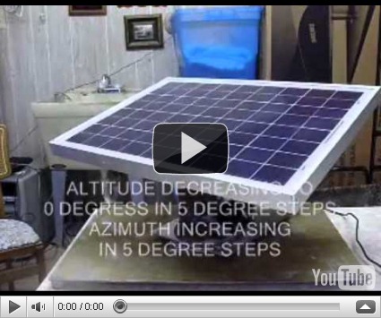
I have just uploaded a slide show to YouTube for an overview of the hardware:

It gives an overview of what the unit looks like. I just received my Jameco 2RPM gear motor and am going to swap it out with the 1RPM one from ServoCity that controlled the altitude (tilt). They look exactly the same, but the ServoCity had plastic gears which stripped out, and the Jameco has metal gears for the same price. I hope it works…
Update: when testing the Jameco gear motor, it stripped gears also.
I could try a sturdier gear motor (probably larger), and raise the hinges to make room for it. The modified desk hinges would likely have to be replaced as the screw holes I bored are specific to the Jameco/ServoCity gearbox. The Jameco/ServoCity gear motors run on just 250 ma current -- which is amazing for the torque they had (800 in oz.). Going larger means more amps and the Baby O can only handle 1 amp continuous per motor.
Another approach may be to hinge the panel in the center lengthwise and let it pivot along that axis. The force required to turn it would be much less than that required by the current scissors lift. I was trying to avoid doing that as it makes the profile taller, more top-heavy and generally less compact, but that may be the simplest solution and I could still use a Jameco/ServoCity gear motor. I will have to sleep on it.
OK. I had an idea how to use a mechanism similar to the one used to open and close louvered windows. This would perhaps allow me to use the same type of motor I have been using. Here is a video of me looking at the mechanism….

I believe the motor could turn a crank to push/pull an offset to the panel (represented by the section of window in the video). The hinges could be moved to a raised center support about 8” above the platen/turntable/lazy susan.
For reference purposes, I am including a drawing of the original design. I will probably use the azimuth motor layout without change (the one with the wheel) , but the altitude will pivot the panel on it’s center axis similar to the tilting mechanism above…
I considered using a linear actuator to tilt the panel, and believe it would be a workable solution, but the cost of $75 for the actuator from firgelliauto.com seemed too high. I decided to try a solution with less-costly gear motors instead. But, in hindsight, after burning out 2 $20 motors – and needing to buy a third, it doesn’t seem so bad after all…
Solar Panel linkage mechanism, version 2:
I just tested the new linkage mechanism, and it works great. Here is a video of the panel tilting…

Here is the Visio drawing…
I now need to order another gear motor. I can test the new linkage with the accelerometer in the meantime.

Calibrating the accelerometer and compass modules:
Both the compass module and accelerometer will need to be calibrated before use. This involves 1. taking readings from these sensors at known angles, then 2. creating lookup tables to return compensated values. See the comments in the get_panel_altitude() and get_panel_azimuth() functions for explanations of how this is done.
I calibrated the accelerometer using a rafter angle square and torpedo level. I connected the altitude motor to 4 c-cell batteries taped together to turn the panel until the bubble was centered in the level for each 10 degree mark on the square and record the reading from the accelerometer at that angle. The readings were entered in the lookup table in get_panel_altitude():

When calibrating the compass module, I turned the panel until the compass module read 0 degrees (there was enough slip to drag the wheel across the base plate), then wrote down the actual compass direction from the pocket compass. I added 45 degrees to that pocket compass reading then turned the panel to match that angle and took another reading, wrote it down and the actual pocket compass reading, and repeated this every 45 degrees until returning back to the starting point (which would be 360 degrees). I then entered these values in the lookup table in get_panel_azimuth().
September 15, 2010
The new azimuth gear motor has been installed and the Solar Tracker reassembled. The following video shows a simulation of the panel tracking the sun. I programmed the microcontroller to turn the panel in 5 degree increments using both motors…
After this test. I put the programming code in what I thought would be its final form (minus adjustment for magnetic declination – only about 1 degree at my location), and brought the panel and it’s AGM battery outside to try tracking the sun. (It must be outside for the GPS to pick up satellite signals.) It simply moved a few degrees and stopped. I will have to do some debugging to find out where the problem is. All of the modules were working individually, so I thought.
September 16, 2010
After some tweaking, and a wire that was connected to the wrong i/o port…the panel is tracking the sun! This is a big moment for me after 6 months of work—well, more play than work as it has been a lot of fun, and I have learned a lot about microcontrollers where before this project, I barely knew what they were. The longer I work with this Baby O robot controller, the more I appreciate how powerful it is…it computes anything you throw at it (just take a look at the sun position algorithm) ,controls two gear motors with PWM, and interfaces with any sensor I have attached to it (provided someone out there made the software to interface with it.) I have learned to apply the saying ‘Google is your friend’ while looking for parts, source code or help in the support forums. In addition to the fun I have had doing this project, I would be tickled if anyone else finds some of this information helpful for their own projects.
So, I will let the panel run a while, then put it in full sun to test the capacity of the 14 AH AGM battery by placing a known load on the 400W Cobra inverter. It will run until the battery is about 10 volts or so, then beep and shut down.
I can then compute from the current, voltage and runtime how much power (watt-hours) the system (panel+charge controller+battery) can produce both during the daytime and at night. This will give me the data needed to make a chart of typical small appliances and portable devices that could run and for how long. At that point, I may begin working on the next version of the solar tracker which will have to be weather resistant in order to work outdoors. The circuitry is currently breadboarded, so that should be moved to a more robust circuit board and the majority of the components encased in an enclosure. I have seen two portable solar trackers which seem to have everything but the panel contained within an inverted ‘can’. The ‘can’ rotates for azimuth and arms extending from the can turn the panel for altitude. I believe I can do something similar to that without too much modification.
September 19, 2010
SOLAR PANEL, BATTERY, CHARGE CONTROLLER AND POWER INVERTER
From the beginning, I wanted to provide only enough power for minimal LED or compact-fluorescent lighting and small device support such as charging for cell phones, iPods, laptop or net book power (about 65 watts) for a few hours daily. The anticipated use would be mostly at night for lighting. In addition, minimizing cost was always a major factor, as I intended such a system to be used in third-world countries. What I finally decided would be adequate to meet those needs contains the following:
- Lavie Solar 12V 20W monocrystalline solar panel
- 12V/24V 10A Wellsee solar charge controller
- 12V 14AH AGM battery (AGM type can be shipped more easily, and will not leak if punctured)
- 12V 400W Cobra DC to AC power inverter with 2 110V outlets and USB port
[[[September 30, 2010
Updated photos to show added switches/junction box.]]]


Tuesday, September 21, 1010
I have just completed the circuit diagram of version 2 of the solar tracker. It shows the separation of components into the indoor package: battery+solar charge controller+inverter, shown above, and the outdoor package: solar panel+robot controller+motors+sensors. Together these make up the whole system. Although this prototype is not weather resistant, it could be designed to be so, by moving the circuitry to surface mount or other integrated circuit board, and protecting the sensors from the weather. I installed the optional rubber caps on the motors, so they are fairly well protected. See circuit diagram below:
[[[Thursday September 30, 2010
I added a junction box with two switches and a fuse to the charger/inverter/battery package in order to easily switch the panel or the charge controller on or off…]]]

This was done with an old version (3.0) of Visio before it was acquired by Microsoft. Not bad for a program designed to run on Windows 95! It just shows how advanced this software was for its time, and it still proves itself to be useful 15 years later :)
The first picture below shows the panel outside for testing. The azimuth motor drives a sponge-tire around the base platform in a circle. There is enough slip so that if the panel is stopped from turning, the gears will not strip. The altitude motor is protected only by the limit switches, which will not protect it if someone would manually tilt it or prevent it from turning when under power. Adding a clutch mechanism to allow slipping would protect it in these cases, or switching to a linear actuator, which has built-in limit circuitry.

The second picture shows the grounding strap near the left hinge so the entire chassis may be used for negative ground. The accelerometer is mounted on the right side of the lid next to the right hinge. The limit switches are mounted just below the right hinge. The compass is mounted on the near side of the breadboard under the programmer cable. The 5A inline fuse and 2A diode are visible on the right above the breadboard. I accidentally reversed the polarity on the previous robot controller and did not want to have to spend another $30 if I made that mistake again, so I added the fuse and diode. This panel contains a diode in the black junction box you see on the left. All connections were made with red 22 GA hookup wire from Radio Shack. For data lines, I wrapped yellow tape around one section of the wire. For + wires, they were already red, so I didn’t have to mark them. – wires are wrapped with a piece of green tape.

The motors are pulse-width-modulated (PWM) for speed control and reversible using two wires each. The Baby O. has a dual H-bridge built-in for motor control. I believe this motor control system is a closed-loop system since the position of the panel in both altitude and azimuth are controlled by feedback from external sensors. The motors will only turn if the sensors indicate that they should. The azimuth motor is controlled by comparing readings from the compass to calculations of the sun’s azimuth. The altitude motor is controlled by comparing readings from the accelerometer to calculations of the sun’s altitude.
September 28, 2010
I let the panel run with a load on it a few days ago. The magnetic declination function was not working right, but declination here is less than one degree from magnetic north anyway. So, I connected a floor lamp with two 52 watt compact fluorescent bulbs and let it run from mid-morning until the inverter shut down. It was a partly-cloudy day. The results are as follows with my 12V, 14AH AGM battery, Wellsee charge controller, and Cobra inverter:
(2 x 26 watts) x (2.66 hours) = 138 Watt-Hours
Based on the above output, I calculated the following runtimes:
| device | volts | amps | watts | runtime (hrs) |
| net book charger | 120 | 1.2 | 144 | .96 |
| cordless phone charger | 117 | .05 | 5.85 | 23.64 |
| cordless drill charger, small | 120 | .5 | 60 | 2.31 |
| cordless drill charger, large | 120 | .54 | 65 | 2.13 |
| cell phone charger | 120 | .02 | 65 | 2.13 |
| 26W compact fluorescent | 120 | .22 | 26 | 5.32 |
Also I have recoded the declination function to get it working with the microcontroller. The revised function has been included in the program documentation.
Tuesday October 5, 2010
I posted the completed project information in the Pololu Robotics Forum and was asked a very good question by one of the forum members:
“How much better is it than just having a solar panel oriented at a fixed angle after counting the energy used by the solar tracking system?”
I did not have the answer at the time so did a little research and some calculations. Here is what I found:
One solar tracker wikipedia wiki states:
‘Compared to a fixed mount, a single axis tracker increases annual output by approximately 30%, and a dual axis tracker an additional 6%.’http://en.wikipedia.org/wiki/Solar_tracker
Wattsun claims:
‘On a year around basis, a dual axis tracker will provide about 35-40% more power output than a fixed rack or pole mounted solar panel array.’http://store.solar-electric.com/waazduaxsopa.html
So you are looking at roughly 35-40% increase in efficiency with dual-axis tracking.
On a partly cloudy day the output of the tracking panel might be about 1A x 12V x 8 hrs = 96W-HR The output of the fixed panel would be 35% less than that or 62.4 W-HR Estimating the power losses to the components to accomplish this gain of 33.6 W-HR: Baby o robot controller: 1/2 maximum i/o current: 5V x .020a x 8hrs = .8 W-HR HMC6352 compass: 5V x .001a x 8 hrs = .04 W-HR DE-ACCM2G2 accelerometer: 5V x .002a x 8hrs = .08 W-HR Parallax GPS receiver: 5V x .115a x 8 hrs = 4.6 W-HR 2 - motors: 12V x .200a x .13 hrs (1 minute/hr x 8hrs) = .312 W-HR Total power losses: .8 +.04 + .08 + 4.6 + .312 = 5.83 W-HR So about 17% of the gain would be lost to the electronics and motors leaving a net gain of 27.7 W-HR That gain would be enough to power an additional 60W compact fluorescent bulb for 1 hour.
<< Contents < Introduction Program Functions >